Concrete Jungle's Fruit Tree Sensors
We’re going to take a break from trying to smell fruit to see instead if we can sense fruit in a more simple way: put a camera in a tree and see what it’s looking at every few days. This is a much more straightforward project: trail cameras and time-lapse cameras are off-the-shelf products. They take photos up to every day, but we can whip up a camera that has a longer interval; something that sends a photo every week would be give us plenty of heads-up. We also want the option of uploading over Wi-Fi or potentially even the cellular network.
The real problem that we face is in power and connectivity. We want something we only have to deal with once a year: we put the sensor in the tree before the season and we pick it up months later when we’re picking the fruit. If we have to visit the tree at any point before that then we may as well not use a sensor.
Battery capacity
If we want something that lasts 3 months (2160 hours) in a tree and a typical 18650 lithium ion battery has 3000 mAh, then our average current draw across 90 days can be 1.38 mA per hour. Not a lot to work with when a single LED can draw 20 mA. We’ll need some way to put our camera to sleep during the downtime, but then how much power draw can we get away with for boot up, snapping a photo and transmitting it?
Battery capacity is quoted in terms of milliamp-hours, but since that’s a unit that’s defined in terms of two other units you have some flexibility in what it means for your project. You could draw 3000 milliamps continuously and your battery will last 1 hour. Or you could draw 1 milliamp continuously and your battery will last 3000 hours, or 125 days.
So if we want to take a photo every week, upload it, and sleep the rest of the time, we could look at our power draw on a weekly basis: if we can draw 1.38 mA per hour for 90 days, then that’s the same as drawing 234 mA per week for 12.8 weeks.
1.38 * 24 * 90 ≈ 234 * 12.8
Making some estimates
So let’s say we’re using a Raspberry Pi Zero with a camera and a Wi-Fi adapter. According to this, we could expect this setup to draw 120 mA at idle. We’ll hopefully not be idling much, so we’ll use 200 mA in our calculations to account for the camera and to give us a buffer.
Then let’s say that it takes 30 seconds for the whole process: boot up, take a photo, send it to twitter, shut down. 200 mA for 30 seconds.
Then let’s say we have some way to shut the Pi down in to a sleep mode for the rest of the time. The Raspberry Pi itself doesn’t have a sleep mode but fortunately the folks at Spell Foundry have come up with a clever solution: the Sleepy Pi. It’s an Arduino that can command the Raspberry Pi to turn on and turn off and then it itself can sleep in a low power state. The Arduino has a real-time clock attached to it, which is very low power and uses a small watch battery, but it does mean it’s sort of like having one alarm clock that turns on a separate alarm clock that then wakes you up.
When the Sleepy Pi is used with this library we can get some impressively low power draws. Like single microamp impressive. Who knows if we’ll get to that low, so let’s assume we draw 200 microamps in sleep mode.
A week has 604,800 seconds. During 30 of those seconds (0.005% of time) we’re drawing 200 mA. During 604,770 of them (99.995% of time) we’re drawing 200 microamps. If we average our power draw over the whole week, it’s identical to drawing 0.21 mA continuously, well under our budget of 1.38 mA. 0.21 mA continuously drawn works out to 35.28 mA per week, so this could technically run for 85 weeks (a year and a half) at that power draw. Or, we could almost even send a daily photo and have basically a trail cam at a fraction of the price.
Connectivity
Since we’re building this in off-season, we’re going with Wi-Fi since we can just put it in one of our yards and test out how it works without committing to a cellular option.
Parts list
- 1 Raspberry Pi Zero
- 1 Raspberry Pi camera with Zero cable
- 1 Sleepy Pi 2
- 1 32 GB SD card
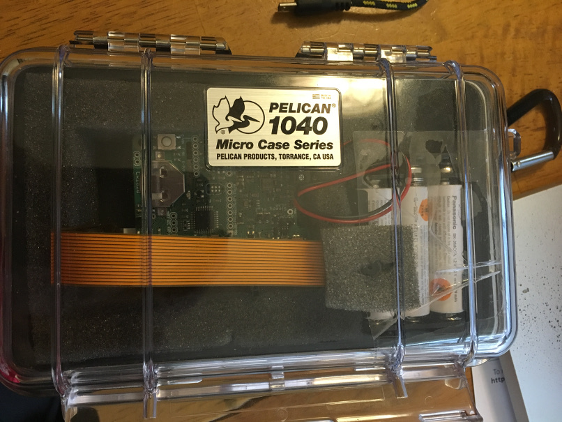
- 1 Pelican case
- 6 Eneloop batteries
- 1 Wi-Fi adapter
- 1 battery holder and terminals
Assembly
Put it all together! Everything plugs in to everything else pretty much as you would expect. Much of the work in making this function is in software. The one hardware change I made was to create a connection between GPIO15 on the Raspberry Pi and pin 9 on the Sleepy Pi.
As is, the Sleepy Pi has a way of turning the Pi on and turning it off, but the Raspberry Pi itself doesn’t have a way to communicate when it’s ready to be turned off (ie, after a photo has finished uploading). You could just tell the Raspberry Pi to shutdown after it has uploaded a photo, but then when you need to change the software, install a new package, etc. you need to communicate to the Raspberry Pi not to shutdown in those situations. So you either come up with a way of preventing shutdown or come up with a way of initiating shutdown.
Working with it
One of the hardest things about dealing with a headless, Wi-Fi-enabled Pi Zero is that if it can’t connect to Wi-Fi then you have to scramble to figure out how to communicate with it. The Adafruit Serial TTL cable can be super useful in this situation, but requires the serial port to be enabled. Normally you would disable this to upload code to the Sleepy Pi but you can re-enable it once you’re done uploading code.
You can also turn on USB OTG mode, but since the Pi Zero has only one USB port, you can only do this when the Wi-Fi adapter is removed.